爱丁堡大学信息学院课程笔记 Software Architecture, Process, and Management, Informatics, University of Edinburgh
Reference: microsoft IBM Software Architecture in Practice (3rd edition), Bass, Clements, and Kazman
What is Software Architecture?
Software architecture is often described as the organization or structure of a system, where the system represents a collection of components that accomplish a specific function or set of functions.
- grouping components into areas of concern (layers): For example, the UI, business processing, and data access.
- focus on interaction between the components and how different components work together.
在书中的定义:
The software architecture of a system is the set of structures needed to reason about the system, which comprise software elements, relations among them, and properties of both. – Software Architecture in Practice (3rd edition), Bass, Clements, and Kazman
架构的关注点在于系统内各个应用和模块的交互和调用。软件架构的设计,需要考虑满足什么样的需求(用户或甲方),如何解决和优化问题(不同的方向各有偏重),操作中如何做选择(在不同的方面平衡,妥协)。
Architecture and design concerns very often overlap - The selection of data structures and algorithms or the implementation details of individual components are design concerns.
没必要强硬区分二者,而应该综合起来看待。某些情况下,决策是自然而然的结构层面的;在某些情况下,决策更多是关于于设计层面,以及设计如何帮助实现架构。
软件架构的定义有如下隐含意思: 1, Architecture Is a Set of Software Structures Three frequently occurring types of structure: – Modular structure: static structure that focus on how functionality is divided up, structured, and assigned to development and implementation teams. – Component and Connector structure: runtime structures that focus on how components interact (e.g. information passing, synchronisation, interference,…) – Allocation structures: mapping to organizational, development, installation, execution environments. (e.g. Components are deployed onto hardware to execute)
2, Architecture Is an abstraction Architecture specifcally omits certain information about elements that is not useful for reasoning about the system - in particular, it omits information that has no ramifcations outside of a single element.
3, Every Software System Has a Software architecture
4, Architecture Includes behavior Behavior embodies how elements interact with each other.
在本课程, 一个软件项目成功与否, 基于如下三点考量: – The software is delivered on schedule – Development costs were within budget – The software meets the needs of users
Contexts for Software Architecture
- Technical: where architecture supports technical activity like measurement, V&V, compliance,…
- Controlling Quality Attributes
- Availability - ensuring there is a system to take over if a system fails.
- Safety - ensuring that the system only behaves as intended and has no additonal behaviour.
- Testability - ensuring:
- elements are clearly able to be isolated
- we know what behaviour to expect of components of the system
- we know how components relate to modules so we can track down faulty code
- We know how components are intended to integrate to give the overall behaviour
- Other qa: performance, usability, interoperability,..
- Design - Patterns, Styles, Domain Specific Architecture (DSSA)
- A DSSA is collection of (pre-decided) design decisions that:
- Capture important aspects of particular tasks (domain),
- Common across a range of systems in the domain
- Typically they will have some predefined structures
- These are not general purpose because they incorporate many specific characteristics of the domain.
- Architectural pattern is a set of architectural design decisions that are applicable to a recurring design problem, and parameterized to account for different software development contexts in which that problem appears.
- Similar to DSSAs but capture less of the behaviour and attributes of the system
- More general because they are intended to abstract a common pattern over several domains.
- Three-Tiered Pattern: State(database)-Logic(Business)-Display(UI)
- Model-View-Controller (MVC): to separate between information, presentation and user interaction.
- Sense-Compute-Control: Structuring embedded control applications
- A DSSA is collection of (pre-decided) design decisions that:
- Controlling Quality Attributes
- Project lifecycle: where architecture interacts with and supports development process
- Lifecycle Models: V-model, iterative models (Boehm’s spiral model), Agile
- Business: where architecture supports organisations, e.g. customer organisations and development organisations.
- Professional: where the role of architect defines requirements and constraints on architects.
Quality Attributes (QA)
Architecture is the right level of abstraction to resolve conflicts between Stakeholders., Bass, Clements, and Kazman")
Quality Attributes specify, usually quantitative, requirements on particular bits of functionality or on the whole systems (e.g. that the system should be available 99% of the time).
Problems With QA 1, Often QA requirements are not “testable”, for example modifiable, usable, dependable or resilient. 2, It can be difficult to map from a concern about the system to a QA. For example, a high failure rate in some transaction could be a performance issue or it could be an availability issue. 3, Communities around a particular quality attribute have developed their own terminology (e.g. security has attacks, performance has events, etc).
The solution for 1 and 2 is to use quality attribute scenarios to provide sufficient specificity to avoid some of these issues.
Quality Attributes Scenarios 场景
A quality attribute requirement should be unambiguous and testable. To specify quality attribute requirements, we capture them formally as six-part scenarios:
- Source of stimulus. This is some entity (a human, a computer system, or a system administrator) that generated the stimulus.
- Stimulus. A condition (event) that requires a response when it arrives at a system. e.g. a user operation to the usability community, or an attack to the security community.
- Environment. The stimulus occurs under certain conditions. The system may be in an overload condition or in normal operation. For many systems, “normal” operation can refer to one of a number of modes. For these kinds of systems, the environment should specify in which mode the system is executing.
- Artifact. A collection of systems, the whole system, or part of the system that is stimulated e.g. the configuration checker in the system.
- Response. The response is the activity undertaken as the result of the arrival of the stimulus. e.g. the configuration issue is identified and then repaired.
- Response measure. how to measure the response so the scenario is testable. e.g. time to detect the wrong configuration and the time to repair.
, Bass, Clements, and Kazman")
Each QA has a General Scenario associated with it that tries to capture the possible components involved in that particular QA. This acts as a template or guide for the architect specifying a specific QA Scenario.
Specific QA Scenarios take account of specific stimuli and measures on response, they capture the specification of the QA for a particular system.
Achieving QA through tactics
Architectural tactics are design decisions to achieve the required quality attributes, more specifcally, to control responses to stimuli.
The focus of a tactic is on a single quality attribute response. Within a tactic, there is no consideration of tradeoffs (differ from architectural patterns, where tradeoffs are built into the pattern).
By cataloging tactics, we provide a way of making design more systematic within some limitations.
An architecture can be viewed as the result of applying a collection of design decisions. A systematic categorization of these decisions:
- Allocation of responsibilities 责任分配: Identifying the important responsibilities, and determining how these responsibilities are allocated to static and runtime elements (namely, modules, components, and connectors).
- Coordination model 模型协调 - Components in the architecture interact with one another via a collection of mechanisms.
- What elements in the system need to coordinate with one another.
- What properties the coordination needs to have (e.g. timing properties, security of coordination, …)
- Choosing the mechanisms (ideally a small number) that realize properties like statefulness, synchrony, delivery guarantees, performance.
- Data model: Every system must represent artifacts of system-wide interest—data—in some internal fashion
- Choosing abstractions, operations, and properties. How data is created and destroyed, access methods, …
- Maintaining metadata that controls the interpretation of the data.
- Organising the data, what kind of system will be used to store it, how will it be backed up, how do we recover from data loss
- Management of resources: hard (CPU, memory, battery, I/O ports…) or soft resources(system locks, software buffers, thread pools…):
- Identifying resources to be managed
- What system element should manage a resource
- 资源共享策略和争端仲裁 Work out sharing strategies and how to arbitrate in contention situations
- Consider the consequences of resource starvation(e.g. Memory).
- Mapping among architectural elements
- two important types of mapping:
- Mapping between different types of elements in the architecture, e.g. from static development structures (modules) to execution elements e.g. threads or processes.
- Mappings between software elements and environment elements, e.g. from processes to specific processors and other hardware.
- Useful mappings include: code to runtime structure; runtime elements to environment; data model elements to data stores.
- two important types of mapping:
- Binding time decisions: introduce allowable ranges of variation.
- This variation can range from design time by a designer to runtime by an end user might allocate a responsibility.
- The decisions in the other six categories have an associated binding time decision: we might want some variability in the resources to be managed determined at run time or we might make the coordination model negotiable at runtime if we want to inter-operate with a range of systems.
- Choice of technology: critical to being able to realize all the other decisions in a concrete system.
- What technologies are available
- What tools are available to support technologies
- How much training will it take to be able to use a technology?
- What are the full range of consequences of the choice of a technology (e.g. it may restrict markets because it is incompatible with some other technologies).
- If the technology is new, how does it fit into the existing preferred technologies for the organisation.
Availability
Availability refers to a property of software that it is there and ready to carry out its task when you need it to be. The availability of a system is usually defined to be the probability it will be there when you ask it to work: $\frac{mtbf}{mtbf+mttr}$
$mtbf$ – mean time between failures: MTBF of a component is the sum of the lengths of the operational periods divided by the number of observed failures: $mtbf = \frac{t}{N(t)}$, $t$ is the cumulative operating time, $N(t)$ is the observed number of failures by time $t$. 假设恒定的故障率 $\lambda$,则 $mtbf = \frac{1}{\lambda}$
$mttr$ – mean time to repair
Availability measures the quality of service in terms of running versus down time
Reliability indicates the fraction of all attempted operations that complete successfully. The reliability of the system is: $R(t) = e^{-\lambda t}$ where the parameter $\lambda$ is called the failure rate. 由于MTBF主要针对可以修复的系统,因此建议针对不可修复的系统(在故障后选择更换而不是修复系统的情况)使用平均故障时间(MTTF),在数学上二者是等价的。 MTTF: Mean Time To (first) Failure, or Expected Life. $ MTTF = E(t_f) = \int_0^\infty R(t)dt = \frac{1}{\lambda}$
Faults, Errors, Failures: A fault is something in the system (e.g. failed component, wrong bit of code,…) that can cause the system to move into an error state when the fault is activated, an error may then eventually cause an externally observable deviation from the intended operation - failure.
Generic Scenario
, Bass, Clements, and Kazman")
, Bass, Clements, and Kazman")
Design Checklist for Availability
Allocation of Responsibilities ■ Determine the system responsibilities that need to be highly available. ■ Within those responsibilities, ensure that additional responsibilities have been allocated to detect an omission, crash, incorrect timing, or incorrect response. ■ Additionally, ensure that there are responsibilities to do the following: • Log the fault • Notify appropriate entities (people or systems) • Disable the source of events causing the fault • Be temporarily unavailable • Fix or mask the fault/failure • Operate in a degraded mode
Coordination Model Determine the system responsibilities that need to be highly available. With respect to those responsibilities, do the following: ■ Ensure that coordination mechanisms can detect an omission, crash, incorrect timing, or incorrect response. For example, whether guaranteed delivery is necessary. Will the coordination work under conditions of degraded communication? ■ Ensure that coordination mechanisms enable the logging of the fault, notification of appropriate entities, disabling of the source of the events causing the fault, fxing or masking the fault, or operating in a degraded mode. ■ Ensure that the coordination model supports the replacement of the artifacts used (processors, communications channels, persistent storage, and processes). For example, does replacement of a server allow the system to continue to operate? ■ Determine if the coordination will work under conditions of degraded communication, at startup/shutdown, in repair mode, or under overloaded operation. For example, how much lost information can the coordination model withstand and with what consequences?
Data Model ■ Determine which portions of the system need to be highly available. ■ Within those portions, determine which data abstractions, along with their operations or their properties, could cause a fault of omission, a crash, incorrect timing behavior, or an incorrect response. ■ For those data abstractions, operations, and properties, ensure that they can be disabled, be temporarily unavailable, or be fxed or masked in the event of a fault. ■ For example, ensure that write requests are cached if a server is temporarily unavailable and performed when the server is returned to service.
Mapping among Architectural Elements ■ Determine which artifacts (processors, communication channels, persistent storage, or processes) may produce a fault. ■ Ensure that the mapping (or remapping) of architectural elements is flexible enough to permit the recovery from the fault. This may involve a consideration of the following: • Which processes on failed processors need to be reassigned at runtime • Which processors, data stores, or communication channels can be activated or reassigned at runtime • How data on failed processors or storage can be served by replacement units • How quickly the system can be reinstalled based on the units of delivery provided • How to (re)assign runtime elements to processors, communication channels, and data stores • When employing tactics that depend on redundancy of functionality, the mapping from modules to redundant components is important. For example, it is possible to write one module that contains code appropriate for both the active component and backup components in a protection group.
Resource Management ■ Determine what critical resources are necessary to continue operating in the presence of a fault. ■ Ensure there are suffcient remaining resources in the event of a fault to log the fault; notify appropriate entities (people or systems); disable the source of events causing the fault; be temporarily unavailable; fx or mask the fault/failure; operate normally, in startup, shutdown, repair mode, degraded operation, and overloaded operation. ■ Determine the availability time for critical resources, what critical resources must be available during specifed time intervals, time intervals during which the critical resources may be in a degraded mode, and repair time for critical resources. Ensure that the critical resources are available during these time intervals. ■ For example, ensure that input queues are large enough to buffer anticipated messages if a server fails so that the messages are not permanently lost.
Binding Time ■ Determine how and when architectural elements are bound. ■ If late binding is used to alternate between components that can themselves be sources of faults (e.g., processes, processors, communication channels), ensure the chosen availability strategy is suffcient to cover faults introduced by all sources. ■ For example: • If late binding is used to switch between artifacts such as processors that will receive or be the subject of faults, will the chosen fault detection and recovery mechanisms work for all possible bindings? • If late binding is used to change the defnition or tolerance of what constitutes a fault (e.g., how long a process can go without responding before a fault is assumed), is the recovery strategy chosen suffcient to handle all cases? For example, if a fault is flagged after 0.1 milliseconds, but the recovery mechanism takes 1.5 seconds to work, that might be an unacceptable mismatch. • What are the availability characteristics of the late binding mechanism itself? Can it fail?
Choice of Technology ■ Determine the available technologies that can (help) detect faults, recover from faults, or reintroduce failed components. ■ Determine what technologies are available that help the response to a fault (e.g., event loggers). ■ Determine the availability characteristics of chosen technologies themselves: What faults can they recover from? What faults might they introduce into the system?
Performance
, Bass, Clements, and Kazman") To ensure resource is effectively monitored and managed.
To ensure resource is effectively monitored and managed.
, Bass, Clements, and Kazman")
Design Checklist for Performance
Allocation of Responsibilities ■ Work out areas responsibility of that require heavy resource use to ensure time-critical events take place. ■ Work out processing requirements. ■ Take account of: • Responsibilites arising from threads crossing boundaries of responsibility • Responsibilities for thread management • Responsibilities for scheduling shared resources
Coordination Model ■ What needs to coordinate. ■ Is there concurrency? Ensure it is safe. ■ Ensure coordination is appropriate for the style of stimulus. ■ Ensure the properties of the coordination model are good for the stimuli and concurrency control?
Data Model ■ Determine what parts of the data model will be heavily loaded or behaves tight time constraints. ■ For those data abstractions, determine: • Would keeping multiple copies help? • Would partitioning the data help? • Is it possible to reduce processing requirements for the data? • Does adding resource help deal with data bottlenecks?
Mapping Among Architecture Elements ■ Does colocation of some components reduce latencies? ■ Ensure components with high processing needs are allocated to big processors ■ Consider introducing concurrency when you map. ■ Consider whether some mappings introduce bottlenecks (e.g. allocating non-interfering tasks to the same thread)
Resource Management ■ Work out what needs high levels of resource ■ Ensure these are monitoredand managed under all operating modes. ■ For example: • Time critical components • Thread management • Prioritization • Locking and scheduling strategies • Deploying additional resource to meet elevated load.
Binding time ■ Look at when you bind. ■ Consider the cost of binding at different times ■ Try to avoid performance penalties caused by late binding.
Choice of Technology ■ Is the technology right to let you meet hard deadlines and resource use (e.g. use a real-time OS with proper scheduling). ■ Do you know its characteristics under load and its limits? ■ Does your choice of technology give you the ability to set the following: • Good scheduling • Priorities • Policies for demand reduction • Allocating processing to tasks • Other performance-related parameters. ■ Does your choice of technology introduce excessive overhead for heavily used operations?
Security
最简单的表征安全的三个特征 - confdentiality, integrity, and availability (CIA):
- 机密性 Confidentiality: Only those who should have access are given access.
- 完整性 Integrity: Data or services are not subject to unauthorised manipulation.
- 可用性 Availability: the system is available for legitimate use.
其他用于支撑 CIA 的特征: 4. 认证识别 Authentication verifes the identities of the parties to a transaction and checks if they are truly who they claim to be. 5. 不可否认性 Nonrepudiation guarantees that the sender of a message cannot later deny having sent the message, and that the recipient cannot deny having received the message. 6. 授权 Authorization grants a user the privileges to perform a task.
Security General Scenario
, Bass, Clements, and Kazman")
, Bass, Clements, and Kazman")
A Design Checklist for Security
Allocation of Responsibilities ■ Ensure all actors have identities ■ Authenticate identities ■ Check authorizations ■ Ensure authorization is required for all such actors ■ Log attempts, successes and failures on all sensitive operations ■ Ensure data is encrypted ■ Ensure responsibilities are allocated to appropriate actors.
Coordination Model ■ Ensure coordination mechanisms use authentication and authorisation. ■ Ensure coordination mechanisms are not vulnerable to impersonation, tampering, interception, … ■ Ensure data involved in coordination is protected using encryption. ■ Monitor level of demand for communication to identify excessive demands
Data Model ■ Ensure there is a valid data model that disallows invalid data flows. ■ Ensure logging of access, modification and attempted access or modification. ■ Data is protected in flight and at rest using appropriate encryption. ■ Ensure appropriate backup/recovery mechanisms are in place.
Mapping among Architectural Elements ■ Explore how different mappings change the way users can access resources. ■ Ensure for all of these mappings the models of access and authorisation are preserved. • Actors should be identified and authenticated • Use appropriate authorisation mechanisms • Ensure logging is enabled • Ensure data is protected by encryption • Recognise impact of attack on resources ■ Ensure recovery from attack is possible
Resource Management ■ Explore the overheads resulting from monitoring, detecting, preventing and recovering from attacks. ■ Analyse how a user can access and make demands on critical resources. ■ Manage resource access to ensure malicious use of resource is detected and managed. ■ Identify the potential for corruption/contamination and how to manage this. ■ Explore the potential for resource use to be used as a covert channel to transmit data. ■ Limit resources used to manage attempts at unauthorised use
Binding Time ■ Explore the consequences of varying binding times on the ability to trust an actor or component. ■ Put in place appropriate mechanisms to ensure trust given binding time. ■ Explore potential impact on resource use, capacity/throughput, response time ■ Ensure appropriate encryption of all data around binding. ■ Explore the potential of variation in binding time as a covert channel.
Choice of Technologies ■ Ensure limitations of technologies are understood and the potential for future compromise is well identified. ■ Ensure your chosen technologies support the tactics you want to deploy to protect the system.
Connectors
Key part of Architectures ■ Connect components and define the rules of interaction between components • Simple: shared variable access; method calls; … • Complex: database access; client-server; scheduler; load balancer ■ Connectors provide: Interaction ducts;
In coding often connectors are implicit, but in software architecture: ■ They are identified and have an identity ■ Capture system interaction (at the level of components) ■ They have a specification that can be complex
Relationship between Connectors and components: ■ Components have application-specific functionality. ■ Connectors provide interaction mechanisms that are generic across different applications. ■ Interaction may involve multiple components ■ Interaction may have a protocol associated to it. The specification of the connector protocols determine: the types of interface that it works with; properties of interaction; rules about ordering of interaction; measurable features of interaction.
Benefits of Explicit Connectors ■ Interaction is defined by the arrangement of the connectors (as far as possible) ■ Component interaction is defined by the pattern of connectors in the architecture ■ Interaction is “independent” of the components
The main roles(services) of Connectors are:
- Communication
- Information is transmitted between components (e.g. message passing; method call; remote procedure call,…).
- Connectors constrain things: Direction of flow (e.g. pipes), Capacity, rates of flow, etc.
- May have other effects e.g. coordination (e.g. blocking I/O)
- Influences measurable Quality Attributes of the system
- Separates communication from functional aspects (components do the functional part).
- Coordination: Controls the timing relationship of functional aspects of the system, e.g. coordinating the arrival of data at a collection of components
- Conversion
- How to get components to interact that don’t have the right means of interaction. 如何让兼容性差的组件进行交互?
- Incompatibilities might be related to: datatypes, ordering, frequency, structure of parameters etc.
- Examples of types of converters: Wrappers (deal with structural issues), Adaptors (deal with datatype incompatibilities)
- Facilitation
- Enable interaction among a group of components that are intended to interact.
- Help manage the interaction
- Examples: load balancer; replication management; redundancy management; scheduler
- Can also relate to coordination, e.g. synchronization (critical sections; monitors)
Select Connectors
Types of Connector: • Method/Procedure call • Data access • Events • Stream • Distributor • Arbitrator • Adaptor
Selection
- Determine a system’s interconnection and interaction needs
- Determine roles to be fulfilled by the system’s connectors: Communication, coordination, conversion, facilitation
- For each connector
- Determine its appropriate type(s)
- Determine its dimensions of interest
- Select appropriate values for each dimension
- For multi-type, i.e., composite connectors, determine the atomic connector compatibilities
Architectural Patterns
An architectural patterns is a package of design decisions that is found repeatedly in practice, has known properties that permit reuse, and describes a class of architectures.
An architectural pattern comprises:
- A context that provides the frame for a problem.
- A problem that is a generalised description of a class of problems often with QA requirements that should be met.
- A solution that is suitably generalised in the same way as the problem. A solution:
- Describes the architectural structures that solve the problem, including how to balance the many forces at work.
- The solution might be static, runtime or deployment oriented.
- The solution for a pattern is determined and described by:
- A set of element types (for example, data repositories, processes, and objects)
- A set of interaction mechanisms or connectors (for example, method calls, events, or message bus)
- A topological layout of the components
- A set of semantic constraints covering topology, element behavior, and interaction mechanisms
Module Patterns
Static Pattern: Layered Pattern
Overview: The layered pattern defines layers (groupings of modules that offer a cohesive set of services) and a unidirectional allowed-to-use relation among the layers. The pattern is usually shown graphically by stacking boxes representing layers on top of each other. Suitable for controlling static aspects of architecture.
Elements: Layer, a kind of module. The description of a layer should define what modules the layer contains and a characterization of the cohesive set of services that the layer provides.
Relations: Allowed to use, which is a specialization of a more generic depends-on relation. The design should define what the layer usage rules are (e.g., “a layer is allowed to use any lower layer” or “a layer is allowed to use only the layer immediately below it”) and any allowable exceptions.
, Bass, Clements, and Kazman")
Constraints: ■ Every piece of software is allocated to exactly one layer. ■ There are at least two layers (but usually there are three or more). ■ The allowed-to-use relations should not be circular (i.e., a lower layer cannot use a layer above).
Weaknesses: ■ The addition of layers adds up-front cost and complexity to a system. ■ Layers contribute a performance penalty.
Component-and-Connector Patterns
Model-View-Controller Pattern
Context: User interface software is typically the most frequently modifed portion of an interactive application. For this reason it is important to keep modifcations to the user interface software separate from the rest of the system.
Problem: • Isolating the UI functionality from the Application functionality. • Maintaining multiple views in the presence of change in the underlying data.
Solution:
, Bass, Clements, and Kazman")
, Bass, Clements, and Kazman")
Other Component-Connector Patterns • Pipe and Filter Pattern • Broker Pattern • Client-Server Pattern • Peer-to-Peer Pattern • Service-Oriented Architecture Pattern • Publish-Subscribe Pattern • Shared Data Pattern
Deployment/Allocation Patterns
Context: – we are concerned with resource use – We might consider flexible deployment of resource – The QAs we care about are sensitive to the pattern of deployment and the use of resources.
Allocation: Map-Reduce Pattern
Context: – We have large quantities of data we wish to treat as “population” data. – This encourages an approach that involves significant amounts of independent processing.
Problem: Where for ultra-large data sets doing some individual processing to a portion of the data set and then sorting and analyzing grouped data, map-reduce provides a simple way of doing this processing.
Solution:
, Bass, Clements, and Kazman")
Other Allocation Patterns • Multi-tier architecture pattern • Cloud architectures
Relationships between Tactics and Patterns
Architectural patterns and tactics are ways of capturing proven good design structures and making them reusable.
Tactics are simpler and more atomic than patterns
• Tactics capture one step to take for a particular Quality Attribute to change behaviour with respect to that QA.
• use just a single structure or computational mechanism, and they are meant to address a single architectural force.
• Tactics can be seen as the building blocks of patterns; Most patterns consist of (are constructed from) several different tactics.
. image from: Software Architecture in Practice (3rd edition), Bass, Clements, and Kazman")
Testability
Testability illustrate QAs from a static perspective.
A system or element of a system is testable if it is possible to test it in the way required by a particular development or maintenance process.
Testability Concerns • Unlike the other QA (availability, performance and security), testability is concerned with the code structure rather than the connector/component view or deployment view. • The system elements we consider are code modules and the relationships are dependencies involved in building the code for components.
Testability General Scenario
, Bass, Clements, and Kazman")
举例 Coverage Concrete Scenario • Source: Regression Tester • Stimulus: Completion of maintenance development to repair a critical bug • Artifact: Modules for the full system • Environment: Maintenance Development • Response: Results from path coverage tool • Response Measure: Path coverage is better than 95% of non-looping paths inside modules
Testability Tactics
- adding controllability and observability to the system.
- Specialized Interfaces
- Record/Playback
- Localize State Storage
- Abstract Data Sources
- Sandbox
- Executable Assertions
- limiting complexity in the system’s designs: If it could be broken into smaller modules with lower complexity that could allow the regression test to achieve higher path coverage.
- Limit Structural Complexity
- Limit behavioral complexity - Nondeterminism
A Design Checklist for Testability
Allocation of Responsibilities ■ Determine which system responsibilities are most critical and hence need to be most thoroughly tested. ■ Ensure that additional system responsibilities have been allocated to do the following: Execute test suite and capture results (external test or self-test) • Capture (log) the activity that resulted in a fault or that resulted in unexpected (perhaps emergent) behavior that was not necessarily a fault • Control and observe relevant system state for testing Make sure the allocation of functionality provides high cohesion, low coupling, strong separation of concerns, and low structural complexity.
Coordination Model Ensure the system’s coordination and communication mechanisms ■ Support the execution of a test suite and capture the results within a system or between systems ■ Support capturing activity that resulted in a fault within a system or between systems ■ Support injection and monitoring of state into the communication channels for use in testing, within a system or between systems ■ Do not introduce needless nondeterminism
Data Model Determine the major data abstractions that must be tested to ensure the correct operation of the system. ■ Ensure that it is possible to capture the values of instances of these data abstractions ■ Ensure that the values of instances of these data abstractions can be set when state is injected into the system, so that system state leading to a fault may be re-created ■ Ensure that the creation, initialization, persistence, manipulation, translation, and destruction of instances of these data abstractions can be exercised and captured
Mapping among Architectural Elements ■ Determine how to test the possible mappings of architectural elements (especially mappings of processes to processors, threads to processes, and modules to components) so that the desired test response is achieved and potential race conditions identifed. ■ In addition, determine whether it is possible to test for illegal mappings of architectural elements.
Resource Management ■ Ensure there are suffcient resources available to execute a test suite and capture the results. ■ Ensure that your test environment is representative of (or better yet, identical to) the environment in which the system will run. ■ Ensure that the system provides the means to do the following: • Test resource limits • Capture detailed resource usage for analysis in the event of a failure • Inject new resource limits into the system for the purposes of testing • Provide virtualized resources for testing
Binding Time ■ Ensure that components that are bound later than compile time can be tested in the late-bound context. ■ Ensure that late bindings can be captured in the event of a failure, so that you can re-create the system’s state leading to the failure. ■ Ensure that the full range of binding possibilities can be tested
Choice of Technology ■ Determine what technologies are available to help achieve the testability scenarios that apply to your architecture. Are technologies available to help with regression testing, fault injection, recording and playback, and so on? ■ Determine how testable the technologies are that you have chosen (or are considering choosing in the future) and ensure that your chosen technologies support the level of testing appropriate for your system. For example, if your chosen technologies do not make it possible to inject state, it may be diffcult to re-create fault scenarios.
Modifiability
Modifiability illustrate QAs from a static perspective. Measure how easy it might be to modify. This is a key area because change incurs cost.
Four key questions: – What can change? – How likely is something to change? – When, where, how and by whom will changes be made? – What is the cost of making the change?
General Scenario
, Bass, Clements, and Kazman")
Tactics to control modifiability
, Bass, Clements, and Kazman")
GPES Example
Version 1: General purpose query facility in each GP system. Version 2: Building a specific piece of business logic for each different query. Think about: – What changes can happen? – How likely is a change? – When, where, how and by whom? – How mush will it cost?
GPES-relevant Scenario • Source: One of the stakeholders e.g. Medicines and Healthcare Products Regulatory Agency • Stimulus: Wants prescribing data on NSAIDs • Artifacts: Code (but depending on the architecture this could be configuration data) • Environment: Operation • Response: Develop the code • Response Measure: Data available 5 weeks after request
GPES Version 1 • Design and validate the query with the Medicines agency. • Code the query. • Test on some systems to ensure it does not have bad effects. • Rollout to all systems. • Make the query available to Medicines agency.
GPES Version 2 • Design and validate the query with Medicines agency. • Negotiate with the GP system providers on the design of the business logic (different in all systems?) • Are the providers the only vendor of such services? Should it go to a procurement? • Validate the queries on each system • Integrate the results • Roll out to all systems • Make the query available to the Medicines Agency
It seems likely that the GPES V2 architecture will not pass the modifiability scenario we describe. Are any of the modifiability tactics appropriate to change the architecture to enable it to pass the scenario? ■ Reduce Coupling is the category of tactics we need to consider. ■ Each of the following offer potential routes with slightly different emphases: • Use an intermediary • Restrict dependencies • Refactor • Abstract common services ■ Defer Binding: can we do this later in the process so it is more likely to be done by a computer than a human? Here this is unlikely. ■ More on Binding Time • Compile time/Build Time: component replacement, compile time parameters,… • Deployment time: configuration scripts that bind at deployment, … • Initialization time: resource files • Runtime: dynamic lookup, service lookup, name servers, plugins, publish-subscribe, shared repositories, (Maybe just in time compilation fits here too)
Design checklist for Modifiability
Allocation of responsibilities Work out how things are likely to change e.g. technical, legal, organisational, social, markets, customers.. ■ Work out what responsibilities change. ■ Try to modularise so a change does not affect responsibilities that span many modules.
Coordination model Look at how changes are likely to affect coordination and try to ensure that the most likely changes impact coordination across a small number of modules
Data model Similar to coordination model – see how a change impacts on data models and try to esnure data model changes span as few modules as possible.
Mapping among architectural elements ■ Looking at potential changes to the system, assess whether some may best be responded to by changing the mapping to elements. ■ Explore issues such as dependencies between elements, data holdings in elements, assignment of elements to processes, threads or processors.
Resource Management ■ Determine how a change in responsibility or quality attribute will change resource. ■ Attempt to localise resourcing change resulting from a likely change to a small number of modules. ■ Look at ways of using policies or configuration to manage resource change more effectively
Binding Time ■ Control choice of binding times so there are not too many combinations to consider. ■ Consider attempting to defer binding to later, balance this against the cost of providing a later binding mechanism.
Choice of Technology Choose technologies that make the most likely changes easier (e.g. choose a technology that allows runtime alteration of critical parameters rather than one where parameters are chosen at compile time) but balance this agains the cost of the different technologies.
Architectural Modelling
Software Architecture is intended to give us control over Quality Attributes. Ideally we’d like to be able to use Software Architecture to predict Quality Attributes. We should be able to build a predictive model of the Software Architecture and use the model to predict QAs. The current situation is patchy…
Some quality attributes, most notably performance and availability, have well-understood, time-tested analytic models that can be used to assist in an analysis. Analytic model means one that supports quantitative analysis.
Types of Analysis • Thought experiment: just a sort of discussion using informed people. • Back of the envelope: using very approximate techniques with unreliable assumptions. • Checklist: collated experience. • Analytic Model: based on sound abstractions – heavily dependent on estimates being correct • Simulation: higher level of detail – less analytic, more concrete. • Prototype: approximate system in an experimental setup. • Experiment: fielded system, simulated load • Instrumentation: measuring the variable of interest
, Bass, Clements, and Kazman")
Analyzing Performance
Models have parameters, which are values you can set to predict values about the entity being modeled. Model can be used to understand the latency characteristics of an architectural design.
, Bass, Clements, and Kazman") Data Needed for the Queuing Model
■ We need the following information in order to model effectively:
• The distribution for the arrival of service requests
• The queuing discipline
• The scheduling algorithm
• The distribution of service times for service requests
• Network characteristics
■ The theory places restrictions on the distributions
• Arrivals are usually expected to be Poisson Distributions specified by arrival rate
• Service times are usually exponentially distributed on the service rate.
• Some queuing behaviors are excluded such as reneging or jockying
Data Needed for the Queuing Model
■ We need the following information in order to model effectively:
• The distribution for the arrival of service requests
• The queuing discipline
• The scheduling algorithm
• The distribution of service times for service requests
• Network characteristics
■ The theory places restrictions on the distributions
• Arrivals are usually expected to be Poisson Distributions specified by arrival rate
• Service times are usually exponentially distributed on the service rate.
• Some queuing behaviors are excluded such as reneging or jockying
Example: MVC, says nothing about its deployment. That is, there is no specifcation of how the model, the view, and the controller are assigned to processes and processors; that’s not part of the pattern’s concern. These and other design decisions have to be made to transform a pattern into an architecture. Until that happens, one cannot say anything with authority about how an MVC-based implementation will perform.
, Bass, Clements, and Kazman") Data for MVC
• Rate of service requests: the View component will service them at some rate.
• Service requests to the Controller are generated by the View component.
• Service requests from the Controller to the View component
• Service requests from the Controller to the model
• Service requests from the Model to the View Component
Data for MVC
• Rate of service requests: the View component will service them at some rate.
• Service requests to the Controller are generated by the View component.
• Service requests from the Controller to the View component
• Service requests from the Controller to the model
• Service requests from the Model to the View Component
Modelling MVC We need estimates of: ■ Distribution of external service demands ■ Queuing Disciplines within the queues in front of each component. ■ Network latencies ■ Transfer characteristics: • View – Controller • Controller – View • Controller – Model • Model – View ■ Scaling to large numbers of components is an issue
Analyzing Availability
One key issue is how long it takes to detect that a failure has taken place. Example is a Broker system.
, Bass, Clements, and Kazman") Hot Spare 热备用 (Active Redundancy)
• Active and redundant both receive identical request stream.
• Synchronous maintenance of broker state.
• Fast failover in the event of failure of the active system.
Hot Spare 热备用 (Active Redundancy)
• Active and redundant both receive identical request stream.
• Synchronous maintenance of broker state.
• Fast failover in the event of failure of the active system.
Warm Spare (Passive Redundancy) • Warm broker is maintained at the most recent checkpoint state. • In the event of failure the system rolls back to the most recent checkpoint. • This is slower than the hot spare approach
Cold Spare • No attempt to synchronise. • In the event of failure the cold spare is started. • The system state is recovered via interaction with other systems (so they have to be resilient to failure in the broker)
Analysis at Different Stages of the Life Cycle
, Bass, Clements, and Kazman")
Architecture in the Life Cycles
前面部分关注软件架构的 technical context。这里开始关注 life cycles。 The role of software architecture is different for different lifecycles.
Balancing Agility and Discipline • Lifecycles generally impose some discipline on the development process. • Software Architectures often feature in Lifecycles as a stage or support for analysis or design • Lifecycles exist because they codify useful patterns of activity and save us time and effort • Agility focusses on getting adequate solutions to stakeholders with less time and effort • We need to balance the discipline of lifecycles against the delivery focus of agility
Lifecycles • Lifecycles underpin development processes by ordering stages and activities. • Any good organisation is always looking to improve its processes so there is usually an ongoing process improvement cycle focussed on making the process better.
V-Model approach works well when you understand the concept and requirements.

Agile Practice • Test-first programming • Refactoring • Continuous integration • Simple Design • Pair Programming • Common Codebase • Coding Standards • Open Work Area
Agile vs. Plan Driven
Early software development methods that emerged in the 1970s - such as the Waterfall method - is plan-driven and inflexible. But having a strong 先期 up-front plan provides for considerable predictability (as long as the requirements don’t change too much) and makes it easier to coordinate large numbers of teams.
Agile methods and practitioners, on the other hand, often 轻视 scorn planning, preferring teamwork, frequent face-to-face communication, flexibility, and adaptation. This enhances invention and creativity.


• Work top-down and bottom-up simultaneously - balance will depend on the size and complexity of the project. • Top-down does architectural work based on things like patterns, product-line. • Bottom-up develops implementation and environment-specific constraints and solutions. • Focus on QAs, scenarios, tactics and processes to 调和 reconcile competing aspects provides a bottomup/top-down link • Balancing commitment and flexibility
Analysis Techniques


Product Line Architecture
One of the early success areas for Software Architecture was the development of Product Line Architectures. Product Line Architecture is an approach to adopt systematic reuse of architectural elements that involves changes in development process supported by specific practices that encourage reuse.
A collection of software-intensive systems sharing a common, managed, set of features that satisfy the specific needs of a market segment or mission that are developed from a set of core assets in a prescribed way.
Software Product Lines are directed by business goals in a particular application domain. • The products in a product line share a software product line architecture • Products are structured by the product line architecture and are built from services and components. • Architercture and components are the core assets used to satisfy the business goals. • Product line leverage commonality and limit variability of the product.
Benefits to the organisation • Large-scale productivity gains • Improve time to market • Maintian market presence (rapidly evolving variants) • Sustain growth • Improved market agility • Better use of skills • Enable mass customisation • Gain control of configuration • Improve product quality • Better predictability of cost, schedule and quality
Costs of a product line
• Architecture: flexible enough to support variation in the products
• Software components: general enough to support variability
• Test plans, cases, data: take account of variation in components
• Business cases: must operate at the level of a product family
• Project plans: generic and extensible to deal with variation
• Tools and processes: must support architecture, variation, configuration, ..
• People, skills, training: need to be skilled in architecture and product lines.
 Product lines spread costs over several products:• Requirements and requirements analysis • Domain model • Architecture and design • Performance engineering • Documentation • Test cases, data, and plans • Skills • Processes, methods and tools • Defect fixing • Components and services
Core Process Activities • Core asset development: improving the base components in terms of qualities, products they support, and architecture. • Product development: identifying and building products to meet market need inside the product line. • Management: monitoring and improving the processes, tools and practices.
Introducing Product Lines • Proactive: Up-front investment to develop the core assets - need to know the market well (maybe have an already established set of products) • Reactive: Start with one or two products and use them to generate core assets. • Incremental: Develop core assets as the business need evolves.
Example: Bosch Gasoline Systems
Goals ■ Competitiveness: • Reduced hardware resource consumption • Reduced time to market for new features ■ Development efficiency • Reuse: Applications can be used across different generations of system; “core” software is highly configurable and is reused via reconfiguration; “Vehicle functions” can be used across gasoline and diesel engines • Easy configuration of software products • Increased planning accuracy ■ Quality • Interface integrity • Reuse of core assets ■ Customer needs • Differentiation by individual software solutions • Clear feature-cost mapping
Component Redesign ■ Focussed on: reuse; simplification of calibration; resource consumption; stabilisation of interfaces (within the architecture) ■ Redesign progressed by: • Analysing existing software inventory: features, sources of variability; relation to product line; document interdependency. • Concept development and design of components: simplification; configurability; architecture driven structure; document relations between features and components; • Baselines for variants of software components: document baselines; implement; maintain up-to-date document and implementation.
Phased Introduction
■ Investigate and customise product line engineering.
■ Design and pilot adequate processes and methods.
■ Roll out and institutionalise in the standard development process.

DevOps
The line between development and operation becomes more blurred and the use of the live environment to test innovations becomes more common. DevOps is a set of practices that span development and operation.
Operations have the direct experience of use of the system – monitoring that use is a way of empirically verifying quality – operations have the data that is used to regulate operations and is essential information for development.
Development is responsible for building in the right monitoring to ensure operations can operate effectively.
DevOps is a set of practices intended to reduce the time between committing a change to a system and the change being placed into normal operation while ensuring necessary quality.
Open Services for Lifecycle Collaboration (OSLC): OSLC is an open and scalable approach to lifecycle integration. It simplifies key integration scenarios across heterogeneous tools.
Traditionally we use test as the way of delivering quality change but we can “shepherd” committed change into use by controlling quantities of change, users experiencing change, results of monitoring than this may offer a better way. Delivery mechanism needs to be high quality: reliable, repeatable, available.
Critical points • Making the decision to commit the code to be introduced into the system. • Transitioning from being under consideration into part of the production deployment that will be used by all users. • Issues is how to have enough confidence to make each of these transitions. Monitoring is critical. • The question is how to ensure the transitions are as reliable as possible.
The extent of the lifecycle • Involves all people involved in the delivery of the service/application • Operations and development people are in continuous interaction. • We need architecture to achieve this. • Microservices architectural pattern is often used.
Microservices
The term “Microservice Architecture” has sprung up over the last few years to describe a particular way of designing software applications as suites of independently deployable services.
The microservice architectural style is an approach to developing a single application as a suite of small services, each running in its own process and communicating with lightweight mechanisms, often an HTTP resource API. — https://martinfowler.com/articles/microservices.html
 Attributes of Microservice Architecture
• Separately deployed units
• Very small service components
• Single purpose function or an independent portion of functionality
• Distributed
• Loosely coupled
• Multiple versions are acceptable
• Asynchronous
• No Orchestration
Attributes of Microservice Architecture
• Separately deployed units
• Very small service components
• Single purpose function or an independent portion of functionality
• Distributed
• Loosely coupled
• Multiple versions are acceptable
• Asynchronous
• No Orchestration
Architecture Evaluation
Evaluation by Designer • The consequences of the decision making regulate how much effort to put into the process – more importance means more effort in evaluation. • Try to use iterative approaches that get deeper in order to eliminate unpromising alternatives early. • Don’t strive for perfection, good enough for the context is usually enough.
Peer Evaluation • Fix on the QAs to consider as part of the review – may be determined by the process or the business case. • The architect presents the architecture to the reviewers – questions are for information. • The review is driven by the relevant scenarios – the architect talks the review team through a scenario demonstrating the architecture meets the requirements captured in the scenario. • The outcome is a list of potential issues with actions: fix, mitigate, tolerate, …
External Evaluation • Means to bring in additional expertise. • May represent some stakeholder interests. • More expensive and difficult to organise so this will often correspond to some major hurdle in the process.
The Architecture Tradeoff Analysis Method (ATAM)
ATAM is a risk-mitigation process. Its purpose is to help choose a suitable architecture for a software system by discovering trade-offs and sensitivity points, to capture project risks. ATAM is most beneficial when done early in the software development life-cycle, when the cost of changing architectures is minimal.
Designed to be usable where: – Evaluators are not expert in the architecture – Evaluators need not be familiar with the business goals. – The system need not be fully developed – There may be large numbers of stakeholders
Participants in ATM • The evaluation team: 3-5 people with designated roles (people may have multiple roles). Team members should be seen to be neutral with respect to the project. • Project decision takers: manager of the project, funder of the project, main architect • Architecture stakeholders: developers, testers, integrators, maintainers, performance engineers, …
ATAM evaluation team roles and responsibilities
Team Leader Sets up the evaluation; coordinates with client, making sure client’s needs are met; establishes evaluation contract; forms evaluation team; sees that final report is produced and delivered (although the writing may be delegated)
Evaluation Leader Runs evaluation; facilitates elicitation of scenarios; administers scenario selection/prioritization process; facilitates evaluation of scenarios against architecture; facilitates onsite analysis
Scenario Scribe Writes scenarios on flipchart or whiteboard during scenario elicitation; captures agreed-on wording of each scenario, halting discussion until exact wording is captured
Proceedings Scribe Captures proceedings in electronic form on laptop or workstation, raw scenarios, issue(s) that motivate each scenario (often lost in the wording of the scenario itself), and resolution of each scenario when applied to architecture(s); also generates a printed list of adopted scenarios for handout to all participants
Timekeeper Helps evaluation leader stay on schedule; helps control amount of time devoted to each scenario during the evaluation phase
Process Observer Keeps notes on how evaluation process could be improved or deviated from; usually keeps silent but may make discreet process-based suggestions to the evaluation leader during the evaluation; after evaluation, reports on how the process went and lessons learned for future improvement; also responsible for reporting experience to architecture evaluation team at large
Process Enforcer Helps evaluation leader remember and carry out the steps of the evaluation method
Questioner Raise issues of architectural interest that stakeholders may not have thought of
ATAM Outputs
• Concise presentation of the architecture – needs to be presentable in around one hour. • Articulation of the business goals – clearly communicated to all participants • Prioritized QA requirements expressed as scenarios – testable QA requirements. • Risks and non-risks – architecture decision that carries risks (or not). • Risk themes – attempt to identify systemic risk by grouping risks into themes. • Mapping of Architecture Decisions to QA requirements – motivating architecture decisions by QA requirements • Identified sensitivity and tradeoff decisions – critical decisions that have significant impact on QA requirements.
 Partnership and preparation: Getting the schedule, agendas and list of stakeholders prepared, preparing necessary documents and presentations, and gettting documents to the evaluation team
Steps of Evaluation Phase
The ATAM analysis phases (phase 1 and phase 2) consist of nine steps.
Steps 1 through 6 are carried out in phase 1
- Presentation of the ATAM approach – remind participants of the approach
- Business drivers presentation – functions; constraints; business goals; major stakeholders; architectural drivers
- Architecture presentation:
- Context for the system
- Static modular view
- Component and connector view
- Deployment view
- Main QA requirements and how the architecture addresses them:
- What has been reused
- Trace of key use cases
- Trace of key change scenarios
- Main issues/risks driving architectural change
- Identify architectural approaches – create a catalogue of patterns and tactics used in the architecture.
- Generate Quality Attribute Utility Tree
- this is an approach to identifying architecturally significant requirements (ASR) by looking through the QAs - identifying particular aspects of the QA that are relevant and any requirements related to that aspect of the QA.
- Each ASR is ranked High, Medium or Low in importance.
- Analyze architectural approaches – look at the most important QA requirement scenarios as identified at stage 5 and probe how the architecture meets the QA scenario.
In phase 2, with all stakeholders present, those steps are summarized 7. Brainstorm prioritization of scenarios – revisit the prioritization for additional scenarios, e.g. a particular stakeholder (performance engineer) might propose a scenario on the response time of the system. 8. Analyze Architectural Approaches – revisit stage 6 but with an expanded and reprioritized set of scenarios 9. Present results – the evaluation group tries to group risks into risk themes to identify systemic issues and results are presented.

ATAM Results • Documentation of architectural approaches taken by the project. • Prioritized list of scenarios • Utility tree • Risks discovered • Non-risks identified • Sensitivity and Tradeoff points identified
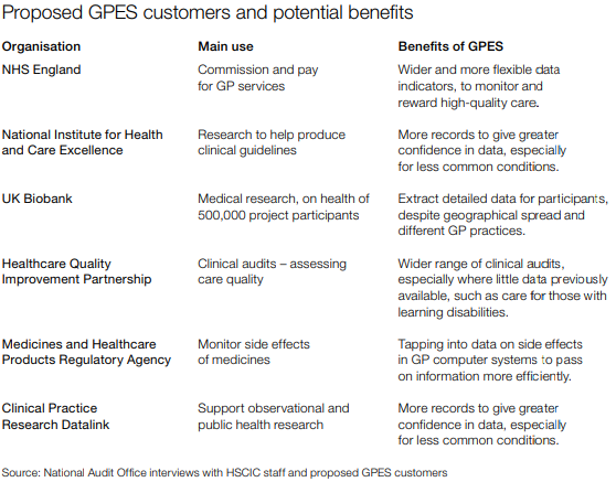
General Practice Extraction Service (GPES)
An IT system designed to allow NHS organizations to extract data from GP practice computer systems in England. This data would be used to monitor quality, plan and pay for health services and help medical research. 数据的请求和返回不需要实时,更多的是定期的请求,一定时间内返回数据。
General practitioner (GP), 全科医生。在英国,每个人都需要注册一个全科医生的诊所,当人们感到身体不适后首先会去联系的自己的全科医生。全科医生只进行有限的治疗,并建议是否有必要去医院看专科医生。每个 GP 都像小公司一样运作,有自己的 GP 系统,为患者保留病患记录。在英国,各种不同的机构组织可能需要了解GP正在做什么,因此需要从所有这些GP系统中提取数据。GPES 系统允许那些已经得到授权的机构组织,通过 NHSCIC(国家卫生和社会保健信息中心)提取各种GP数据。因为不同机构需要的信息不同,NHSCIC 需要研究制定如何提取指定的数据,并运行 GPES 系统从英国的所有GP系统提取数据。GP 可以从四种不同的 GP 系统中四选一。而 GPES 的挑战在于整合来自各个不同系统的GP的数据。
问题
- The project has been significantly delayed and many customers have yet to receive data.
- Mistakes in the original 采购 procurement and contract management contributed to losses of public funds, through asset write-offs and settlements with suppliers.
- Only one customer, NHS England has so far received data from GPES. The time needed to design a new type of extract and restrictions in the contracts severely limits HSCIC’s ability to provide data to those who request it. It is unlikely that GPES in its current form can provide the NHS-wide service planned.
Data Extract Issue
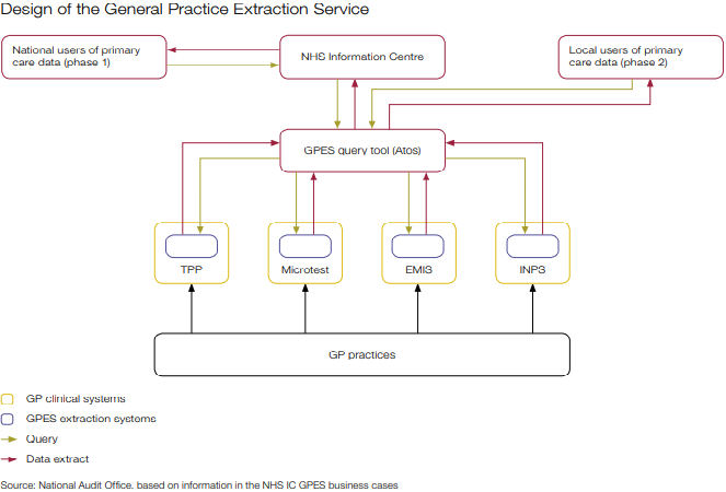
- NHS did a technical review of GPES in early 2011, which recommended several significant changes to its design. In the original design, each GP system supplier would use a common query language as part of their extraction system. This would allow the NHSIC to design a single extract centrally using the query tool, which all GP clinical systems could understand.
- The technical review recommended an alternative where each supplier would be free to develop their own query methods. New queries would no longer be designed in the query tool using a common language, but would instead need to be designed as logical ‘business rules’ and sent to GP system suppliers to implement.
- The NHSIC decided to abandon both the GPSOC contract approach and the common query language, as they could not agree either with the Department and GP system suppliers. They then procured the extraction systems by negotiating direct with the GP clinical system suppliers.
- NHSIC is using a non-competitive procurement approach, plus the changes in design, contributed to the restrictive process for designing new extracts.
- The HSCIC, has continued to use the GPSOC framework to require data sharing between NHS systems. The new framework, effective from 2014, says that principal clinical system suppliers must provide an interface method for third-party systems to use. This would improve interoperability between systems in GP practices and the health community.
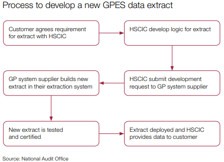
- The HSCIC cannot do the wide range and scale of data extracts the NHS requests, because of the design of the GPES system and restrictions in supplier contracts. Customers have requested over 100 different data extracts from GPES, but the HSCIC estimate they will be able to design only 24 new extracts in 2015-16.
- Figure shows a summary of the HSCIC’s process to develop a new extract, each of which the supplier designs and programmes from scratch. The HSCIC have limited flexibility to amend extracts once developed, for example to change a time period and the specific organisations it will extract data from.
- GPES will continue to operate in the short term, as its data is critical for determining payments to GPs. Its coverage of all practices in England cannot currently be replicated by other primary care data extraction systems.
- However, limited capacity and the difficulty of developing new extracts deters wider use. The HSCIC has acknowledged there is unlikely to be a long-term future for all or part of the GPES. However, they intend to reuse parts for a replacement system if possible. The HSCIC estimate that they will achieve less than two more years of use from the GPES in its current form, in contrast to the five-year minimum lifetime assumed for new IT systems.